Search the Community
Showing results for tags 'electrics'.
-
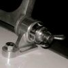
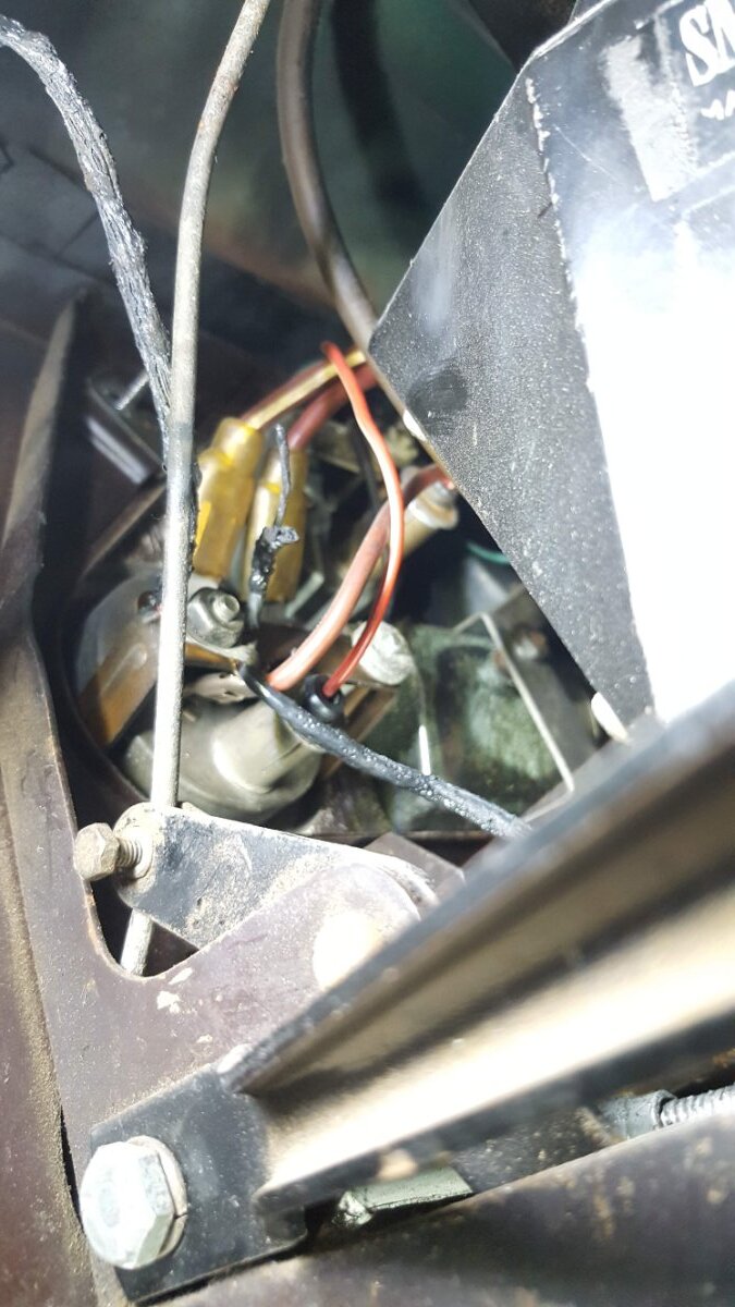
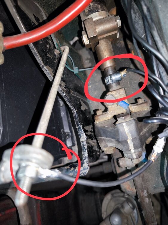
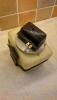
Dear TR Forums colleagues, I just wanted to post an alternative way to provide ground to the steering column. Today I had my MOT and yesterday evening, while testing the car, I noticed that the horn had stopped working. Much to my surprise, I discovered that the lower silent lock did not have the bypass cable, so the steering column had no ground. To add to the problem, when tested bypassing the silent ick, I realized that the steering rack had no ground... As the horn was working before, I can only asssune that ground was reaching the column trough the cabling collar around the steering wheel and it stopped working when I adjusted the steering wheel so that the steering wheel hub would not rub on the cabling collar... So, with no time to do a proper repair, what I did was to attach a round metal hose clamp around the steering column in the area closer to the firewall and the battery box, loose enough for It not to turn with the column, but tight enough to provide electric contact. I then attached a cable to the hose clamp and connected It to ground. It worked perfectly and I passed my MoT. It is a bit of a PITA to bypass the lower silent lick, so I am considering refining the system and making it permanent by using a copper ring. This would have the advantage of accesility. I attach a picture with the hose clamp and the connection to ground highlighted with a red circle. I hope someone may find this useful
-
See update. NOS original Triumph bulb holders for the front and rear side marker lamps of TR7/8 cars. Rimmers call these 'Cruise Lights' and their part number is 13H5270 or 13H5270L Both no longer available. Peter W
-
Before I begin this post, I am aware that the newer fuse ratings are continuous and not blow. The question therefore is fuse ratings in 'old money'. The TR4/4A workshop manual states that the fuses in the fuse box should be 25A blow (12.5 continuous) but both Rimmers and Moss are selling 35A fuses for both the TR4 and 4A (I am assuming for the sake of this that these fuses are 35A blow). The only fuse that is 35A blow 17.5A continuous in the workshop manual is the horn fuse. Consequently I have been using 25A in the fuse box (with no problems). Usual reason for a fuse to blow is a short to earth and both a 25A and 35A would blow in that instance. Just wondering when it was decided by the 2 suppliers mentioned that it was ok to fit the 35A (blow) in place of the 25A (blow) mentioned in the workshop manual. Unfortunately the TR4A handbook fails to state the fuse rating. The Haynes manual follows the workshop recommendations. I have also got the TR4/4A owners workshop manual by Kenneth Ball (Autopress) and that also states that the fuse carrier has 2 x 25A fuses and the horn is 35A (again blow rating). Does it matter which fuse is fitted? Personally I am sticking to the 25A fuses to err a bit on the safe side. (Rather blow a fuse than cook the wires). Also does anyone have a quick DIY way of telling whether a fuse marked simply 35A is blow or continuous. Presumably the 2 types have differing resistances but the resistance is too low for a standard ohmmeter to differentiate. I have tried a simple Wheatstone bridge and a simple Kelvin bridge arrangement to compare fuses with no success. I have a few of these fuses that I might end up ditching because I can't tell what they are. Keith
-
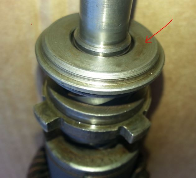
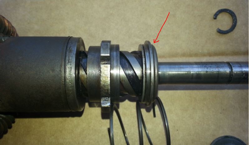
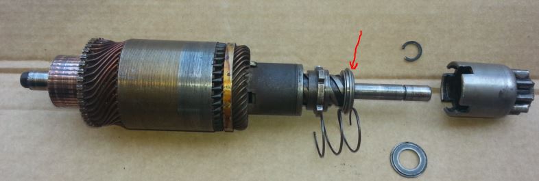
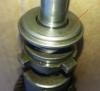
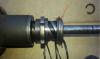
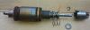
Good afternoon! I'm trying to dismantle my Lucas "bomb" type starter motor M4185 V164. The motor turns fine and pushes the bendix out but fails to turn the engine. I think that the coupling, (sleeve and rubber drive item#57 in the Moss catalogue) must have delaminated and I need to replace it. I've never seen a starter like this before and I can't dismantle it. I've removed the bendix gear OK but I can't get any further. My "Autobooks" manual refers to a pin and at nut that I don't seem to have. I've attached some pictures with where I've got to. I cannot find how to remove the collar (arrowed). I wonder if it has a circlip inside the collar but I can't actually see one nor see how to get at it if it is there! Once dismantled I'd appreciate any tips on the rebuild please. Any suggestions most welcome. Many thanks Regards Andrew King Swanage TR3a TS75982L
-
Ok one for the electrical gurus......... To set the scene (apologies for length of this)..... I have a tr4 converted to negative earth with a lightweight Revington 40amp alternator fitted. I have a battery cut off switch wired into the ignition circuit. I also have the revington auxiliary wiring loom which gets its power from the battery side of the cut off switch and is switched via the ignition and a relay) Amongst other bits and bobs (interior lights, windscreen washers, radio,map light all low amp stuff) , that loom powers an electric revotec fan which is wired via a relay (there is also an override switch for this wired using a switching relay). I have also fitted relays for the dip and main beams and there are spot lamps and fog lamps. These are wired via relays to come on when the relay is powered by the dip (fog) or main beam (spot) with override switches on the dash which effectively make an earth to latch the relay when in the on position. The power for the lights etc comes from wires connected to the starter solenoid via a further auxiliary fuse box. The issue is that the ammeter shows a positive charge when the lights are on and more positive charge when the fog or spots are on (say 15 to 20 amps). Is thus a result of the source of the lights' power (ie the starter solenoid) or something else? Checked alternator with multimeter- runs about 12.8 volts tick over and gets up to 14 and a bit when revved so doesnt seem to be over charging. The needle on the ammeter rises with engine revs- it seems to be measuring load rather than battery charging. Alternator is three terminal type- big post for current and one to ignition and one to warning light. Light behaving normally -ie on when ignition turned on but off when running. Charged up battery fully to check wasn't in need of amps and still did same thing. No problem starting Any thoughts? Bob
-
I have had an indicator buzzer fitter for quite a few years to my 73 TR6. This was wired across parallel to the flasher unit. Recently I have had problems with the indicators and the buzzer. I have changed the switch to a tested good one. Changed the flasher unit and rewired it. Earthed all the rear lights with additional earthing points and all seemed ok. However I found applying the brake affected the buzzer making it sound weak, a bit like a strangled cat!! I found removing high power LED stop /tail and fitting normal filament bulbs stopped the problem. A long Club run on Sunday was completed with no issues. When re fitting the LED stop / tail bulbs the problem returns with the buzzer but indicators still work ok at normal speed. Switching on headlights does have any effect to the buzzer. I find it hard to believe that the LED bulbs could cause a large voltage drop but I don't know what to investigate next other than trying another set of LED bulbs. MARK
-
On the 'to do' list for my recently acquired TR6, is the installation of up to 6 relays for various existing and new components. Unlike my 3A, I am hoping the install these together, on the inner wing, close to the fuse box and 4 way block rather than scattered about the car. All but one will need need to be earthed at that location. My question, is how best to do this? Seems to me that these are the options (but there may be others): - earth each relay individually by screwing a cable from each separately to the body panel. - earth each individually but use ring connectors on each earth cable going to a single new connection to the body panel. - piggy back each earth outlet from one relay to the next with a single final cable being screwed to the body panel (not keen on this) - use a busbar to which the earth cable from each relay is attached. So, friends what have others done and which solution is thought to be best. As ever, many thanks. Miles
-
Has anybody fitted a clock to a TR4 and if so whats the best way to connect it all up. I recently purchased a rectangular Jaeger clock that will fit into the ash tray aperture with a little bit of fiddling. As I don't smoke it seems a good place to fit a clock which will be a lot more useful than the ashtray. It also allows a back light to be fitted. So linking up the light to the other instrument lights is no problem but I'm not sure of the best way to connect the clock; via a direct wire to the battery with an inline fuse or via the fuse box. Any advice would be appreciated.
-
The indicators have stopped working on my 1974 TR6 can you please give me some advice on how to troubleshoot this. The flasher unit looks new - its round not oblong, but of course that doesn't mean it is working. I also dont know if this is important but when I tried the indicators in the garage there was a click on the passenger side behind the dash and then nothing. It hasnt done this again turning the ignition switch on and off. The fuse is ok. Could a blown bulb cause the problem? I'm not an electrician but I know how to use an ammeter and follow basic instructions. Any help would be appreciated. Cheers Rob
-
Hi everybody Kenlow fan controls are good because they have an automatic function when the water temp gets too high and a manual override and a fan teltail light to enable the driver to manually switch on the fan and also be aware when the fan is running very good but the fiddle of getting a copper tube into the upper waterways is difficult and difficult to seal What other methods are used to give the auto control with manual override and tell tale light? I have used kenlows for years but feel it might be time to move on Would appreciate more modern solutions that others have found to work Hopefully MichaelH
-

Electronic ignition working when wrongly connected !!!
MARK posted a topic in Technical - all models
Cleaned the plugs and checked plug leads late, the night before going on a run on my TR 6 which has an Acuspark electronic ignition unit in the distributor. It ran badly the next day , losing power as the revs rose and coughing , spitting (Triple Webers). However managed about 100 miles leading a group of friends. Back at home I checked my TR6 and found that had accidently connected both wires of the ignition module to the negative terminal on the coil (Aldon Flame Thrower). Correctly connected with one wire of ignition unit on pos. terminal of coil and my car got its mojo back !!! . How did it even start let alone manage 100 miles at reasonable speeds? Can anyone out there explain how this is possible? P.S Don't fiddle with your car late at night when tired !!!!!! MARK -
HA HA, ha ha, b*ll*cks. Went out for a lovely drive to a local pub yesterday early evening, enjoying the new alternator, narrow belt and electric fan. Had a good pint of landlord sitting in the sun. Empty lanes on the way back driving into the setting sun, then whoof - a load of smoke from under the dashboard. I impressed Hazel and myself by isolating the battery within about 5 seconds (even though the switch is deep in the footwell on her side) and having the fire extinguisher out in about another 10 (but I may be exaggerating). I didn't use the extinguisher as the smoke cleared. After checking as many things as I could see, I tentatively started it again and it seemed ok. A passing car enthusiast said he saw some smoke coming of the exhaust and as we had just been over a big pot hole he theorised it could have been a dollop of oil thrown onto the exhaust. I liked to think he might be right. Just as I got home I noticed the indicator warning light was not working, so today I started doing a more detailed check under the dashboard. As I started wiggling wires underneath, pow, a spark and lots of smoke again. Isolator was off in nano-seconds this time and extinguisher already by my side. On my back with my head somewhere it shouldn't naturally be I managed to see that the black earth wire from the indicator warning light went to the little knurled nut on the speedo back, and then on to a little post on the back of the ammeter bracket. This section was frazzled and broken - presumably the cause of it not working yesterday. The earth wire then continues behind the H frame somewhere and is frazzled. From the passenger side I can see what looks like a frazzled wire going somewhere with other wires, but I can't be more specific than that at the moment. From the pictures I can see a brown and brown/white wire going into the top of the ammeter (which is in accord with my wiring diagram), and another brown wire appears to go on the bottom of the ammeter, but is just about touching the little post the earth wire appears to be attached to. The nut on the post is lose, so it seems to me the pot hole yesterday and my subsequent wiggling things today may have caused a short. The other pic is from the passenger side where I think I can make out two frazzled wires (or could be the same one twice). I suppose I am going to have to remove things to get better access to see what's going on, but I'd appreciated any initial thoughts on what may have happened. In particular I obviously can't see where the normal earthing points are from the wiring diagrams, and I don't know why there are 3 wires going to the ammeter (plus one that looks like it's for the ammeter light). The great thing is of course that it happened not far from home, we got home, and the car and us are not burnt out, though it is slightly concerning that something like this can happen without blowing fuses or something. Thanks for any help. Ali.


-
Since I wrote about wiper-motors in TR-Action it's probably no secret that I rebuild the early Lucas wiper-motors. About 10% of those that come my way have a problem with the armature. This is not a problem with the DR2 type, because I have a good stock of new armatures for these, left over from other activity. Ask if you need one. But the more common DR3A type armatures are a problem to get. Now and again I get lucky and find one for £20. Sometimes I get forced to pay £40-50. This really makes a motor rebuild uneconomic. Even if I find an NOS one there is no guarantee it will be in good shape. Often they have rusty shafts and other corrosion, having sat too long in damp packaging. Anybody on here who finds he has a commutator ploughed up by the brush arms, will be in the same position as me. Except I'll be on eBay bidding too. Apart from damage from being run with worn brushes, there is the dreaded "black-wire" problem. Here is one I fixed recently for a Register member: This happens if they are powered up, but stalled or jammed for any reason. At least 10A will flow and the temperature gets high enough to melt the solder joints. You can see this on one of the tags. This is the inside of the motor. You can see the witness left by evaporated varnish: Armatures like this continue to run. May do so so for quite a while. Annual MOT and running about to summer shows and you'd be OK, most likely. But one dark wet night on the motorway and after running hot for a few hours, don't bet on it. I DON'T SELL THESE. No doubt many others on eBay would. Be careful ! So I have a dozen laying about and a worsening supply problem. I asked every motor rewinding-shop I could find, to quote for rewinding them. NOT ONE REPLIED. I am rather glad they didn't bother. The reason is that they know what I now know. It's not just the wire. The copper commutator-segments are moulded into the phenolic bush. This is probably the hottest spot. When you strip one down this happens: This is probably a more likely cause of terminal failure than the wire. A segment gets loose, catches the brush and game over. Rewinds are POINTLESS on these, unless you fit a new commutator. Nobody has these, which is why nobody would quote me. To be fair I asked in the RFQ for new commutators, just to shut out the rogues. I thought about making new commutators. I'd do this if I just wanted one, maybe! I considered other things like nicking them from DR2's. These are not exactly the same but close. I could get them off but I'd scrap the shaft. It would mean lathe-work and this would be slow. Then I found these: New, not identical, but very close. They would be cheap too, were it not for shipping, VAT, customs-handling etc. i took a £100 punt and got ten. All the ploughed up commutators got fixed in an afternoon. Four perfectly serviceable armatures from the scrap heap, economic even if I count labour at a commercial rate. Brilliant! Now then, what to with the black-wire ones? You can all guess what comes next I expect.
-
A well known register member passed a DR3A wiper motor to me recently. It's got a 130 degree gear-wheel and came from a TR3A most likely. It ran OK, but took more current than they should do, indicating it was a bit stiff. It always amazes me how well these have stood up and I've yet to see one that is beyond repair. But there are a couple of common failures and so here I dismantle this and show how to restore and improve these. It came looking like this: http://www.flickr.com/photos/90670218@N04/12569961143/ http://www.flickr.com/photos/90670218@N04/12569960223/ There is a bit more corrosion underneath than usual but this is insignificant. Four screws hold the top-plate, one missing but I've got new ones. Slip off the Horseshoe clip and C-clip, don't loose the tiny thin shim from the crank-pin. http://www.flickr.com/photos/90670218@N04/12569957713/ This is a carbon-braush set, in good order, note the orientation of the "grooves". http://www.flickr.com/photos/90670218@N04/12569956373/ The 130 degree gear, arm and cone-washer http://www.flickr.com/photos/90670218@N04/12570304214/ http://www.flickr.com/photos/90670218@N04/12570301184/ Store the armature carefully to prevent breaking any wires. If the carbon brushes wear down the two arms will cut grooves into the copper I can "skim" these but this one is good. The black ring is normal. http://www.flickr.com/photos/90670218@N04/12570297144/ This shows one of the common problems http://www.flickr.com/photos/90670218@N04/12569945753/ The arm is bent up. Happens if you try to remove connection to the wire-rack without releasing the Horseshoe-clip. The arm will scrape on the cover and the wire-rack won't go smoothly into its tube. You can do without this extra friction. It takes a few wiggles to get the big self-taps out of the pole-piece. Go easy they could break off and this would be awkward to fix. http://www.flickr.com/photos/90670218@N04/12569923693/ After 1 hour in Caustic-soda. Wear protection! http://www.flickr.com/photos/90670218@N04/12593543515/ http://www.flickr.com/photos/90670218@N04/12593984004/
-
Slightly off topic - working on my 1984 Mini 25 which has a ballast wire system - The PO was a bit of a "maverick" Brake callipers fitted upside down (bleed nipples pointing down!) 2 brake compensators fitted etc, etc - because of this and as I'm working through the ignition system, can someone confirm that using a multimeter set to 20k OHMS, testing the Positive terminal and the HT lead terminal of the coil, if I get a reading above 1.5 (1500) that the COIL is a NON ballast type coil ?? The reading I get is 6.35 so I suspect that this is a standard coil (I cannot see any markings or labels on the coil) Thanks Matt
-
How many amps should a standard alternator deliver? Is there a way of checking performance other than turning the headlights on and looking at the ammeter?JJC
-
Hi, I got some questions if i could share pictures of the spot lamps brackets I made for my tr2 instead of the bumper brackets. Liked the look allthough I will return the original setup now i'm fully restoring the car. Here's a picture of the lamps in situ, taken on Francorchamp. I used the origal brackets as a template to create a new bracket to which I welded a cilinder. I used a solid bar and hollowed it, so i had 1 side closed. I drilled the closed site to the size of the SFR700 lamp stud. The holes in the brackets were meant for the mount to hold the Lucas horns like the OVC276 (never got to it to fit them...) The hole in the back is used for the wires to get a clean look on the front Mind you, these are milimeters ! After the welding i had them powder coated. It still looks good after 4 years in front of the car. Tip: buy covers for the lamps, I was too late, the first chips are there.. Have fun creating. Any questions, just let me know. Disclaimer: Never intended to create exact copies of the real ones, so there will be differences from the real deal.
-
Hello, not strictly technical................ I am flogging a couple of old Bosch lights on Fleabay and there is interest from Japan, initial search brings up costs in excess of £200, with additional packaging the parcel will weigh in at 4kg and be around 600mm x 400mm x400mm, can anyone help?, cheers, Andrew
-
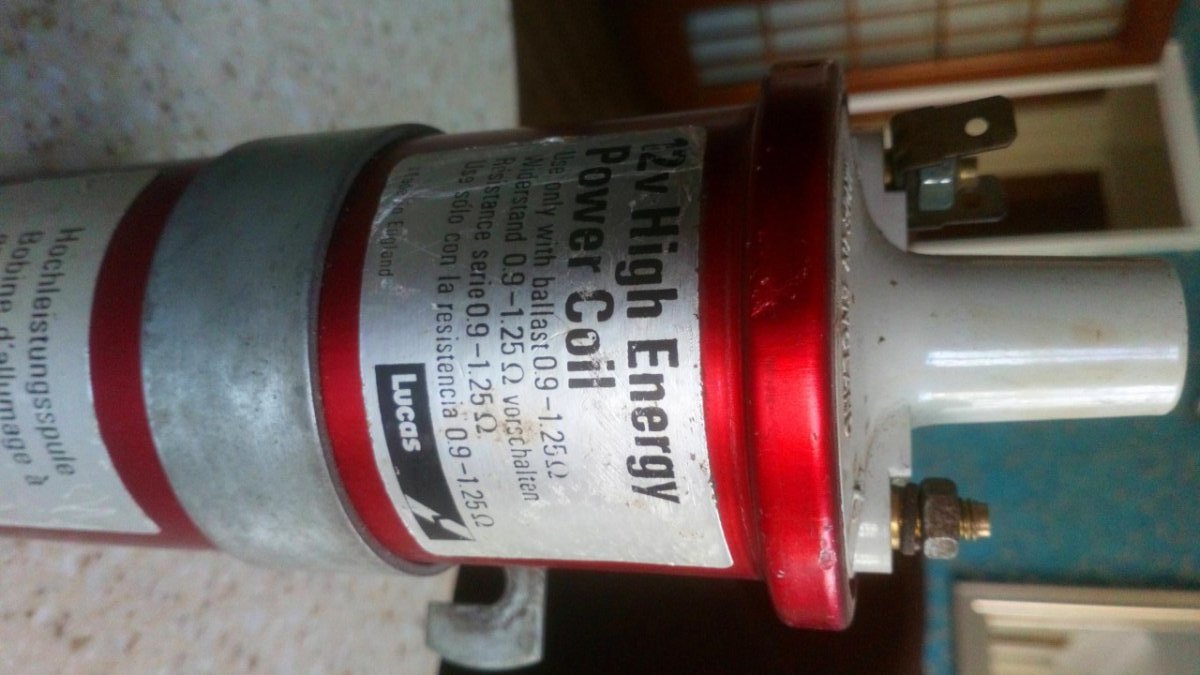
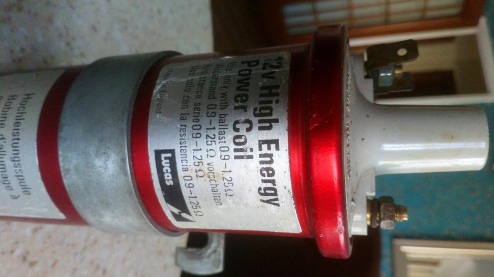
A Coil Conundrum ! I've had this original Lucas red coil for some time with the thought it might make a good spare for travelling etc. Problem is I'm not completely certain about its suitability for a CR TR6. The label says "for use only with 0.9- 1.25 Ohm ballast" and I'm unsure what ballast a CR TR6 loom comes with - could someone advise please? It also claims to be a "12v High Energy Power Coil" and on a CR TR it will only see 12v for the start-up, then approx 8-9v I think when running. I've measured the primary resistance and it reads 2.3 Ohm, thats pretty much half way between what I think is normal reading for a ballast coil (1.5 Ohm) and a full 12v coil (3 Ohm) so again I'm not sure if its a good 'un. Any thoughts would be appreciated. Cheers Bob
-
What is the expected voltage from an alternator?? The ignition light goes out on my car and the voltmeter on the dash slowly creeps up to just over 13, checked with a digital meter on the battery terminals and depending on revs the meter only goes up to 13.5 ish volts? kc
-
I've seen a few posts over the past year of folks, like myself, looking for a wiring diagram for CR cars. Usually we get (well intentioned-ly) sent toward the advance autowire link that seems to have diagrams for every TR5/6...except ours. I managed to get pdf of a pdf of a copy of a scan... that I've tidied up into a colour wire diagram to mimic these. I originally formatted at A3 on PPT and converted to pdf which seemed to magically transform it to A4, but it should blow up ok. There are some bits for German market cars I've left out for simplicity (extra rear lights & hazard lights) but if anyone would like a copy of the original file, or the ppt I hacked together so they can use it as a base to document their own "enhancements" or "PO embellishments" please feel free to PM me with your email & I'll send them through. Righto MT EDIT: now here: CR Series wiring diagram
-
A question for any of the electrical experts out there ....... My TR6 alternator is simply marked as 14v 45A A115 type (it has a Lucas Electrik sticker with 24 026 on it). The concern is I'm only seeing 13v across the battery terminals at tickover, and only 13.8v when revved harder. If I turn the headlamps on the voltage drops back towards 13v again. I think this is 1v less than it should be, doesn't sound much difference I know but the battery isn't that old and I'm having to separately charge it. The alternator is under 2yrs old btw. Has anyone taken an alternator voltage reading I could use for comparison please? Cheers Bob
-
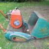
Hi All Was going to pop my refurbished washer bottle back on my resto project. Looks nice and clean with repainted bracket and home made strap. Cleaned all the motor up before giving it a test and err dead. So should it work by just connecting to a 12v, i would assume it would, but no. Completly disasambled it and it looks fine to me and the motor spins freely when the shaft is spun, but clearly i know nothing. So any tricks to get and old electric motor such as this kicked into life? I've had a look at the usual retail suspencts and this type of motor (see pic) seems unavailable only a Lucas GWW125, which although cheap as chips is the wrong shape and i'd prefer to get this one working. Cheers Keith
-
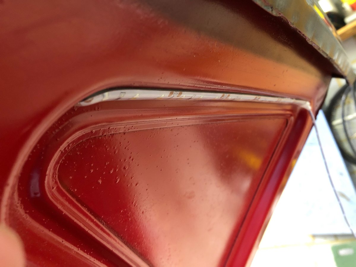
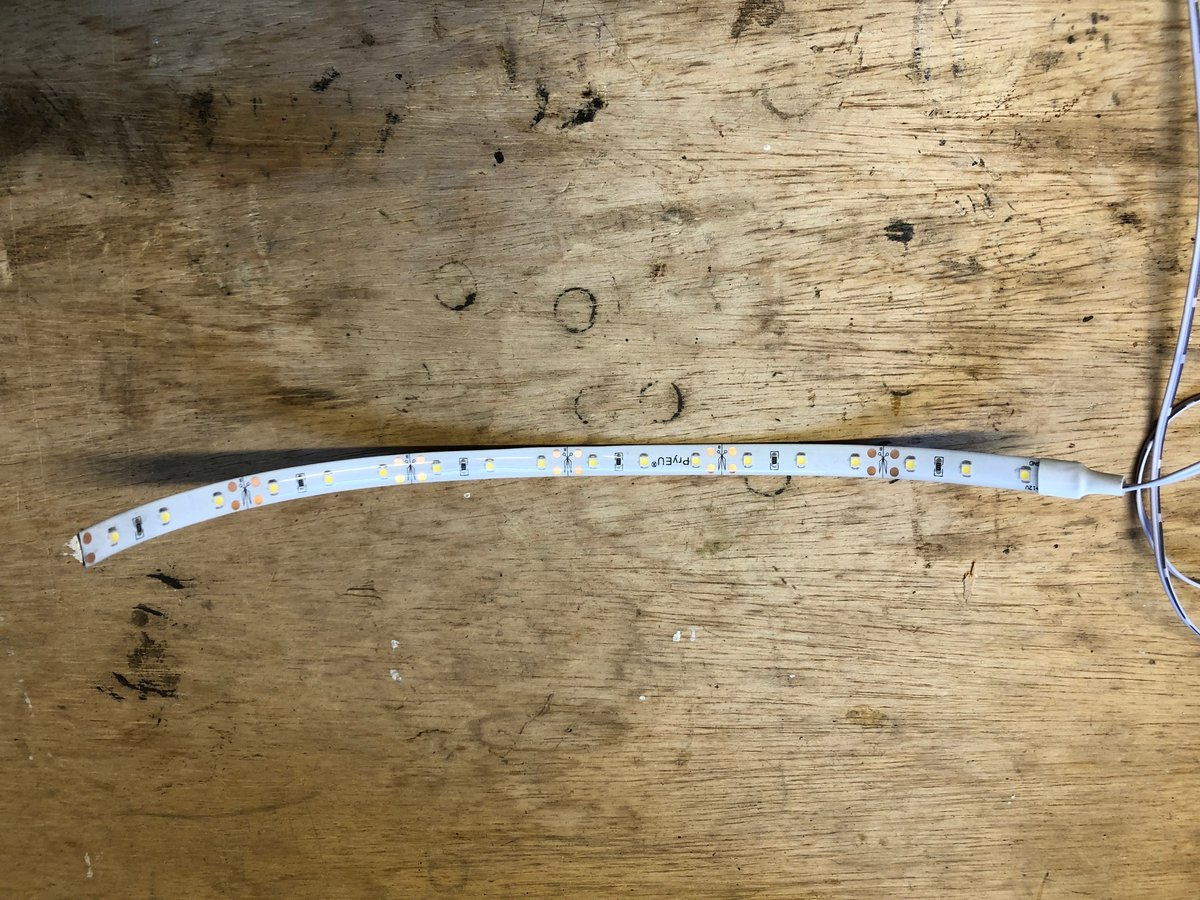
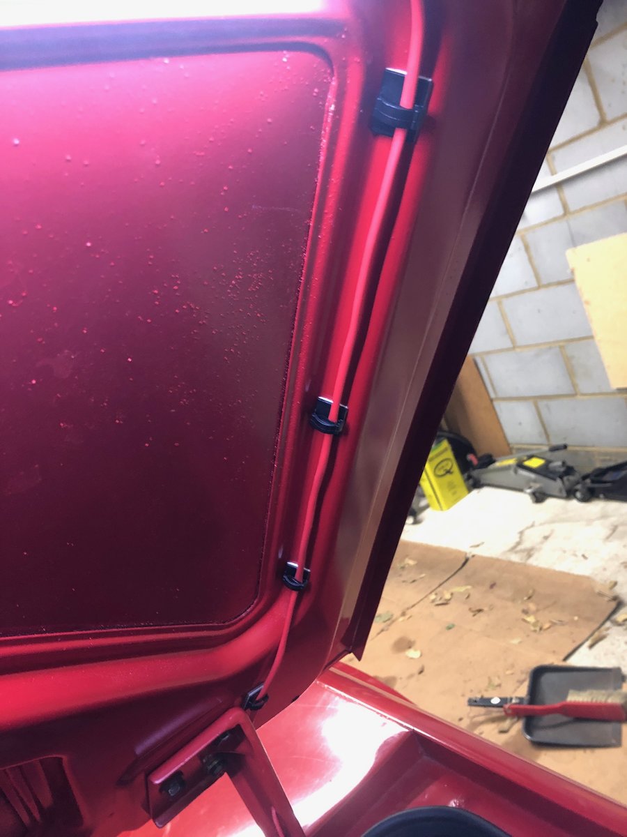
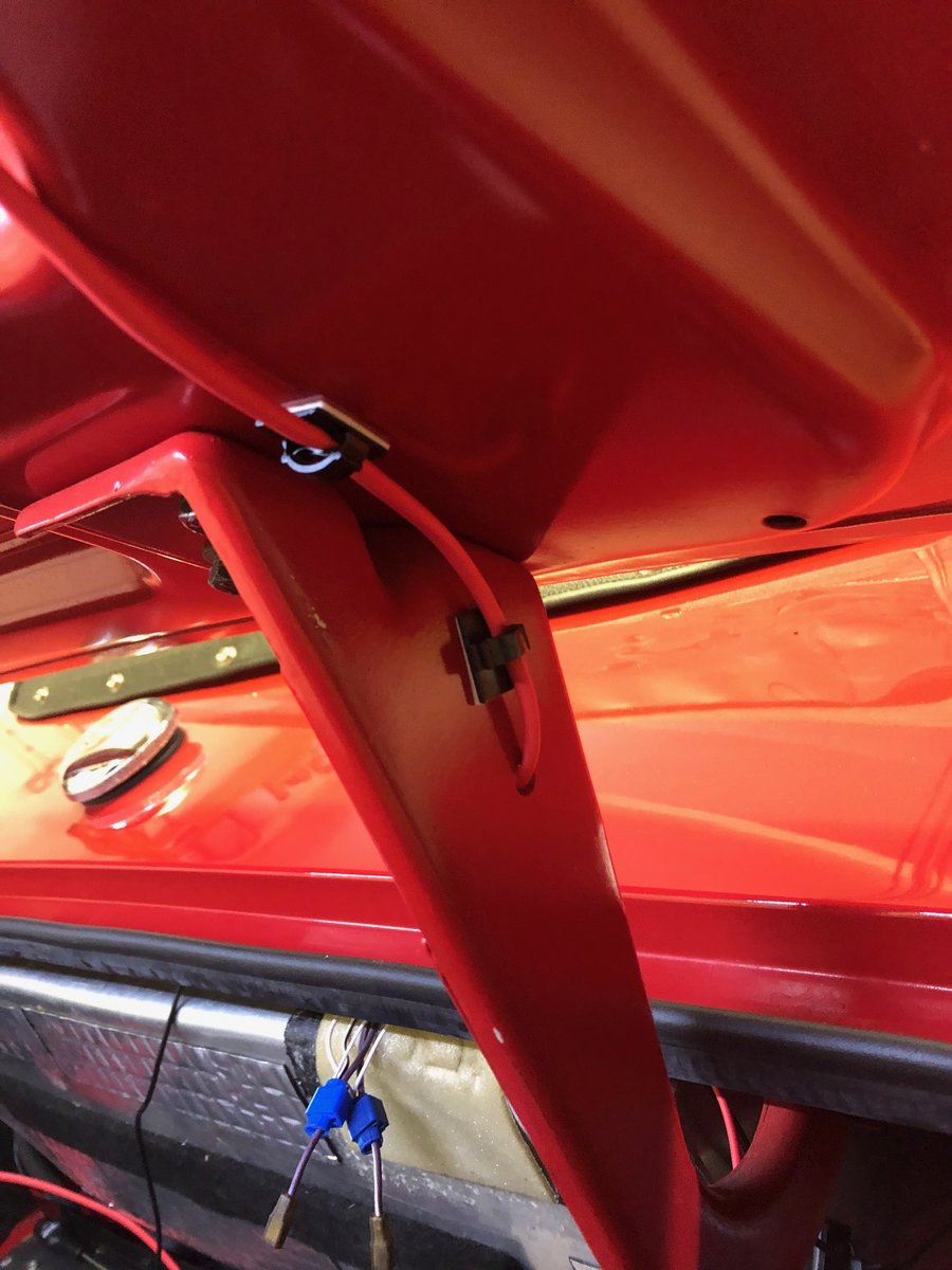
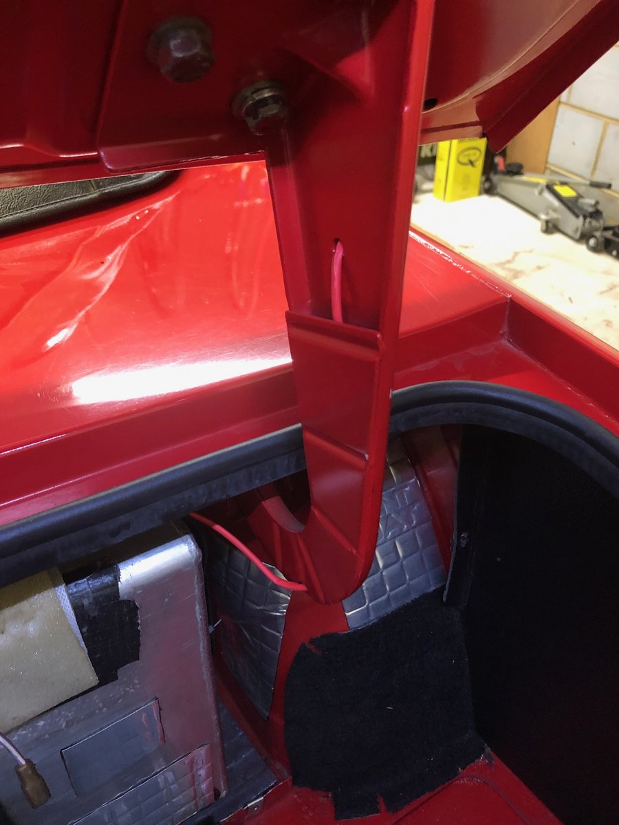
I thought it would be useful to post some words and pictures on how I recently fitted LED strip lights to vastly improve the illumination in my boot. Hopefully the pictures tell the story, but here are some points to note: The c.45 degree edge on the boot frame provides an ideal mounting point for self-adhesive LED strips 30cm long as the angle means they flood the boot with light when the boot is open. I used red heatshrink to protect and camouflage the wiring to the LEDs. The wires are fed into the space behind the boot card by using the boot hinge assemblies and connected to the existing wiring using plastic self-stripping cable lock connectors - not my usual connector of choice, but OK for this non-critical low current wiring. The LEDs I used had a 1metre wire already attached, but don't seem to be available any longer - however search for "LED white strip 12v 30cm" on and you will find what you need. I hope this is of use to someone. Cheers Steve PS) I can't claim the credit for the idea - I was inspired by seeing a similar arrangement under the bonnet of Mark Bulford's TR4!


-
I see there have been a few posts recently around this area so apologies but given the consequences of me getting this wrong I wanted an unambiguous thread. When I ordered my new wiring loom for BUO, CP series TR6, I spec'd an upgraded relay fed supply for the fuel pump, and feed for electric fan. All good I thought .............no the fuel pump and fan feeds were taken directly from the back of the starter motor ie the non load side of the ammeter so if it (the ammeter) was of any use when it was fitted to the car in '72 it not doing much good now. I'm planning to pull my current ammeter apart and fit the front bezel and 'mask' to one of these https://www.ebay.co.uk/itm/Smiths-Volt-GAUGE-52-MM-Diameter-Real-Item/124102619368?_trkparms=aid%3D999002%26algo%3DURGENT.LUI%26ao%3D1%26asc%3D20140502134130%26meid%3D08b0fa52eb6f41c18adec7086db7055d%26pid%3D100043%26rk%3D1%26rkt%3D1%26so%3Dlastwatched%26sd%3D202761281899%26itm%3D124102619368%26pmt%3D0%26noa%3D1%26pg%3D2508447%26brand%3DSmiths&_trksid=p2508447.c100043.m2062 I know it will then show 'amps' when I'm measuring volts but think I'll be able to manage the conversion in my head. My understanding is connect the 'in' and 'out' of the ammeter together and connect this to the +ve side of the voltmeter and then earth the other side. Could somebody just confirm for me please.