Search the Community
Showing results for tags 'tr4'.
-
I guess that most of us suffer to a greater or lesser degree from the wiper blade that rests just off the screen acquiring a "set" which means it doesn't wipe properly when pressed into service. Some people park their blades vertically on the screen but that can be a faff as you have to do it every time you park up and it's not clever on a dry screen. What I do if it looks like rain is to swap the blades over. Then the flat one is on the driver side (for RHD cars) and the one with the set seems to wipe OK on the passenger side. Give it a whirl, it works for me and I've been out in some serious rain just lately.
-
If they made 40,000 TR4 cars what year would CT 38463 be made? 1964 or 65? is there an amount of cars produced by year from 1961 through to the TR4A introduction?
-
Am looking for a set of pistons and liners for my TR4, (see buy sell trade) I see revemmups have a set at £320 and are +20. ( Haven't looked elsewhere yet ) The size of piston @ liner sets vary considerably, and reach £700 for max size ones before a block modification is needed, almost double the cost of the +20 ones. In a standard car, how many seconds would the expensive sets remove from the 0 to 60 time? We wont be going racing or rallying. Any advicewould be helpful, and have you an unused set perhaps, if so let me know.
-
I want to replace the steering wheel with an original one. What is the size of nut? 13/16 does not fit right.
-
Folks: I added a remote brake servo as part of my rebuild. I've bled the brakes 2 times and the pedal still goes down to the floor quite a bit. Is there a special method to bleed brakes if you have a servo installed ? Many thanks, JB
-
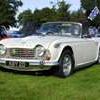
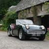
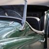 Here are some images of the cars and the venues at the 2013 Vintage Triumph Register Convention / Triumphest at from October 2-6, 2013, courtesy of one of the attendees, David Gunn. The hosts this year were the Triumph Travelers Sports Car Club (http://www.triumphtravelers.org/), the Triumph marque club in the Bay Area. I wasn't able to attend -- it's sort of like having the TRR IWE be a 4000 mile round trip for the weekend. And I live in the middle of our country! You'll see a powder blue TR3 in some of the photos that did make the ride (on a trailer) from our local club to the west coast. Dedicated Triumph folk. You'll also see the club scene is a little more inclusive over here -- it's hard for us to draw a line between "TR" and "Triumph" in the US. Heck, our local show is the "All-British Car Show" where any British marque of any age is welcome. Enjoy the pix. http://www.flickr.com/photos/dgunn/sets/72157636342731323/ PS. Excuse the tags. This system is kind of stupid right now -- where's the "all models" tag?
 -
Thinking of fitting headlamp relays. Not sure whether to run a new supply all the way to the lamps and fit relays near the lamps or site the relays near the dip switch and thus use most of the existing wire to the lights with a new supply only going to the relay somewhere in the footwell/bulkhead. The existing lights seem fairly bright so doesn't seem to be much of a voltage drop and main aim is to help out the switch, also the bulkhead relay is less "invasive". However, part of me thinks it is better to use more new cable with a higher current capacity. Also, if the relays are up front, are there issues with keeping them weather proof? Where do people site them? Thanks in anticipation Bob
-
I am just in the process of welding new floors and sills into my 4 ( i know I have been doing it for a while, ) I have the floors and inner sills tacked in and the tub sitting on the chassis while I line up and tack in the outer sills. What I need is a few close of photos of the correct gap around the doors and particularly along the bottom of the door. With so few 4s floating around in our part of the world, its hard to get a good reference. Close ups of the base of the A and B pillars would be great as well, I realise they will need leading but I am interested in seeing the finished product. If some one wouldn't mind getting some good close ups of the door and guard gaps and emailing me I would appreciate it. My email is jim.davis at harcourts co nz. Thanks
-
Folks: I just finished up all my wiring to the car as I've converted it to negative earth/ground and installed the Pertronix electronic module for negative earth/ground TR4. Turn the key and smoke started pouring out of distributor and it looks like I fried the electronic module. I cannot figure out what I wired up wrong. Here's what I did: Changed car to negative earth Installed Pertonix module for negative earth/ground cars - it came with a RED and BLACK wire Hooked up the wire per the Pertronix instructions Attached the BLACK module wire to the coil negative (-) terminal Attached the RED module wire to the coil positive (+) terminal Attached the original TR4 WHITE ignition wire from key switch to the coil (-) terminal (This was not in the instructions so assumed to leave the same??) I am also using a Pertonix Flame thrower coil Any ideas what I wired up wrong ? Off to order a new module now ! Thanks for any help...JB
-
Hi all: Both the heater blower switch and wiper switch on my das have 3 connectors - 2 next door to each other and one connector underneath. Something like this: | | _ Can someone tell me which wire goes to which connector on the switches: Wiper Switch - which connector does the BLACK/GREEN wire connect to and also the BLACK ground/earth wire ? Heater Blower Switch - which connector does the GREEN wire from the voltage stabilizer and the GREEN wire from the heater fan connect to. Many thanks...JB
-
Hi everyone, My TR4 has spacer plates about 5 mm thick outside of the brake drums (haven't confirmed the same setup on front, but seems likely as front wheels are slightly wider than arches). This is obviously to widen the track. Can anyone advise where I can get replacements? Have checked Moss, Rimmer & Revington without success. Studs are double threaded, so outer thread needs to be at least 5 mm longer than standard Best wishes. Willie
-
I have bought the revington lightweight alternator conversion for my tr4 and I think the wiring etc all makes sense per their instructions. However, I have a couple of questions re the wiring generally. I have read elsewhere that is it a good idea to run an extra heavy gauge wire from the alternator to the battery (or starter solenoid if the run is shorter which it will be) to ensure that the existing wiring doesn't impeded the charging capacity of the new alternator. The alternator has three terminals - one for the lamp, one to the ignition (IG terminal) and then the output terminal post. If I ran the extra wire presumably this would be an extra wire on the output post. otherwise revington wire this post to the battery via the ammeter. is the extra wire a good idea. I have fitted the extra loom kit from revington already. This is wired from the starter solenoid, via a cut out switch. Presumably this helps the wiring as any lamps, fan etc goes through their new loom wire to the fuse box and draws current independently of the existing wiring that goes via the ammeter to the battery. is my understanding correct and what effect does all of the above have the the ammeter and it's reading? Regards Bob Ps I have fitted relays recently per Roger's suggestion ( see post on tr4/4a forum) and these are wired from the starter solenoid via the ignition cut off switch)
-
Hi all..me again... Trying to piece my scuttle vent rod back together. I see where it connects to the vent door and also where it connects to the open/close knob onside on dash. For the life of me I can't figure how to get it through the car body. I have passed the mister tube through a hole underneath the dash. Does the rod go through this hole also ? I can't seem to find a straight line of site for the rod from the vent cover back to the open/close knob Anyone have any ideas ? I might have this car done just in time for winter to start here in cold Chicago ! Tks a bunch...JB
-
 Hi guys A quick question on setting valve clearances on a four pot running standard cams etc. I went through this process following initial start up of our rebuilt engine, but I think I may not have done it properly: I measured the clearances (when cold) for both the inlet and exhaust valves on each cylinder when that cylinder was at TDC. I thought this would be ok given that both valves would be well and truly closed at this point of their cycle. I now note (having RTFI’d) that you are supposed to carry out this adjustment when the cam lobe for the valve you are adjusting is exactly opposite (180deg off) the tappet (rule of 8’s and all that). The question is – do i need to redo the clearances? According to my basic geometry calcs, each of my cam lobes would have been approx 135 degrees off the tappet instead of 180 degrees. I am interested to know what the geometry of the cams are – for what portion of their circumference are they round? Finally – I also assume that doing it the way i did would only (at worst) result in having greater clearance than specified and hence poor running rather than any valve seat burning issues. Thanks in advance for your help. Malcolm
 -
A friend ( well known in certain TR circles.......) has fitted his prop shaft with the sliding joint at the diff end, will this cause a problem, and why ( trying to avoid one word answers ). On the face of it we cannot see one. It is a non IRS car, but would the same apply for an IRS one? Thanks Mike
-
Came across a quantity of 8-32 captive nuts that look OK for this otherwise unobtainable item. Anybody got a door card off at the moment and can measure accurately the size of the rectanglular punched hole where these fit. Dont want to dismantle a door card just to measure this.
-
Giving the gauges a good clean,can we obtain the rubber seals behind the glass ,also the gauge itself. ROY
-
It could be of interest to someone http://bc.kijiji.ca/c-cars-vehicles-classic-cars-Triumph-roadster-project-W0QQAdIdZ531795748 Cheers Graeme
-
Have been working on the chassis, shortening the tubes to accept the body extensions which I have tacked on ready for the "Proper welder" who arrives tomorrow. Ive also received 2 plates from Colin at CTM, the splash plates, he has handed then R/H and L/H but where they fit is a mystery, has anyone a pic which would help please. What does B1 signify? and a small crack on the top of the rear legRHS just behind the shock absorber.
-
Folks: I bought a new TR4 inner steering wheel column from TRF ( I screwed my original one up dismantling it) and also new TR Revington outer column nylon bushes. The inner column seems to be a little tight and actual turns the outer column a bit when I turn steering wheel. Is there some trick to make the inner column spin more freely in the inner column bushes ? Not sure because everything new ?? Should I have put a lot of grease on inner column when I pushed it into the outer column bushes ? Thanks for advice JB
-
Almost finished fitting the floor and new sill, just a bit of tidying up to do. Have cut out the floor on the other side but this side is more difficult, for I wish to retain the outer sill, which is in VG condition. I have started to drill out the spot welds and having done this previously with what I thought were the correct spot weld drill bits, and found it an awful job, this drill has done all the holes so far is still sharp and doesn't wander like the other almost flat faced drills I have used. This drill is just amazing. Also to complete the job you need a good collection of music. With a grand Amp. An imaginary Golden friend to swear at who doesn't answer back. Finally, to complete the job its handy to have the number of someone who can get you out of the sh1-, when it all goes wrong. Havent called JUST yet
-
Hi all I bled the brakes on the TR4 and seem to have a couple leaks at the brass union where all the lines come into. Seems to be leaking at the brake switch and the long nut pressure thingy ( don't have my manual with me so not sure what this part called. Couple questions: 1) Is there supposed to be a gasket between the union and the long pressure nut thingy ? I checked parts books and didn't see one 2) since the union is brass I only nipped up the brake switch and pressure nut. How tight should these be ? 3) Should I add some sealant to the threads ? If so any recommendations? 4) any other thoughts greatly appreciated As always thanks for your help JB